Recent Post
- 2026-07-01 16:31:05

Article
In the domain of precision CNC machining, the difference between a quality part and a scrap component often hinges on the machine tool’s geometric and dynamic performance. While modern CNC routers and machining centers—whether used for woodworking, stone carving, or metal fabrication—are built to exacting standards, their accuracy degrades over time due to wear, thermal deformation, and mechanical shock. One of the most effective diagnostic tools for quantifying this degradation is the ball bar tester. This instrument, though simple in concept, provides a wealth of data about a machine’s positioning, circular contouring, and servo system performance.
The ball bar tester operates on a straightforward principle: a precision-length bar with magnetic ball ends is placed between the machine spindle and a precision cup mounted on the worktable. The machine is programmed to execute a circular interpolation path, typically in the XY plane, while the ball bar’s linear variable differential transformer (LVDT) or optical encoder measures minute deviations from the programmed radius. These deviations, recorded as the machine moves through a full 360-degree arc, reveal systematic errors such as backlash, scale mismatch, servo lag, and squareness issues.
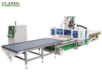
For woodworking and stone carving equipment—where Roctech machinery, for example, is widely deployed—ball bar testing is particularly valuable. In custom furniture production, a nesting CNC router like the Roctech RCA1224 must maintain positional accuracy within ±0.05mm over a 1220×2440mm worktable to ensure proper fit of cabinet components. A ball bar test can identify whether a machine’s rack-and-pinion drives, commonly used for high-speed X/Y movement, exhibit periodic error from gear tooth engagement or whether the Z-axis ball screw has developed backlash from repeated drilling cycles.
The typical ball bar test procedure begins with setup: the magnetic cup is precisely positioned on the worktable, and the ball bar is attached to the spindle using a magnetic tool holder. The machine must be homed, and the test radius is programmed—usually 100mm or 150mm for most CNC routers. The feed rate is set to a moderate value, such as 1000mm/min, to avoid dynamic effects that might mask geometric errors. The machine then executes the circular path in both clockwise and counterclockwise directions, while the ball bar’s software records radial deviations at each angular position.
Interpreting the resulting polar plot requires experience. A kidney-shaped pattern typically indicates squareness error between X and Y axes—common on gantry machines where the cross-beam is not perfectly perpendicular to the side rails. A sharp spike at the quadrant transitions suggests backlash in the drive system, often from worn ball screws or loose couplings in the transmission chain. A gradual increase in deviation with angular position may point to scale mismatch, where the X and Y axes have different effective pitch or scaling factors.
The data table below summarizes typical ball bar test results for a mid-range woodworking CNC router, compared against industry-accepted tolerance thresholds:
| Parameter | Measured Value (μm) | Acceptable Tolerance (μm) | Machine Issue Indicated |
|-----------|---------------------|---------------------------|-------------------------|
| Circular Deviation (clockwise) | 45 | ±50 | Within tolerance |
| Circular Deviation (counterclockwise) | 52 | ±50 | Marginal servo mismatch |
| Backlash (X-axis) | 12 | ≤10 | Slight drive wear |
| Backlash (Y-axis) | 8 | ≤10 | Acceptable |
| Squareness Error | −15 arcsec | ±10 arcsec | Gantry misalignment |
| Reversal Spikes (X-axis) | 18 | ≤5 | Ball screw preload loss |
| Servo Gain Mismatch Ratio | 1.12 | 1.00 ± 0.05 | Axis tuning required |
The data reveals that while the machine’s overall circular deviation is near the acceptable limit, the squareness error of −15 arcseconds indicates that the gantry’s cross-beam is slightly tilted relative to the side rails. This condition, if uncorrected, would cause cumulative positioning errors in large sheet nesting operations. Furthermore, the X-axis reversal spikes of 18μm point to insufficient ball screw preload, which could lead to chatter during heavy cuts.
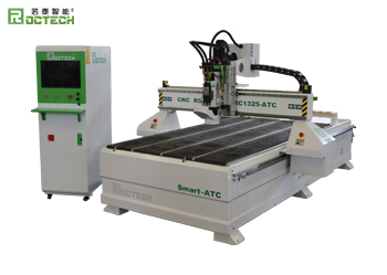
For manufacturers like Roctech, whose product lines include five-axis machining centers such as the RCF1325, ball bar testing is integral to both quality assurance and field service. During factory acceptance testing, each machine undergoes a ball bar test under ISO 230-4 standards to verify circular contouring performance. In the field, service technicians use ball bar tests to diagnose issues reported by customers, such as inconsistent part dimensions or visible tool marks on finished surfaces. For example, a Roctech technician might identify that a customer’s machine—operating
Looking for more information about our CNC machines and services? Contact us today.
Contact
Previous:Six-Sided CNC Drilling Centers: The Backbone of Automated Panel Furniture Production
Next:Not


Precision Assessment in CNC Machining: The Role of Ball Bar Testing for Machine Tool Accuracy - Roctech® have advanced technology for CNC Router,cnc router cabinets,Roctech already have 15 years experiences of cnc router technology.-© 2023 Roctech® Machinery Co.,Ltd. - All Rights Reserved Website Terms Of Use ● Privacy Policy ● Cookie Policy