
Plasma Cutting Bevel Compensation: Precision Adjustment for CNC Thermal Cutting Systems
About Us / Author:ROCTECH Engineer Team / Published: Jul 15 , 2026 / Last Updated: Jul 15 , 2026
Abstract
Plasma cutting, while highly efficient for ferrous and non-ferrous metal processing, inherently produces a kerf angle—commonly referred to as bevel or taper—due to the directional nature of the plasma arc and gas flow dynamics. This phenomenon becomes particularly problematic when cutting thicker plates or when edge squareness is critical for subsequent welding or assembly operations. This article examines the root causes of angular deviation in plasma cutting, presents methodologies for mechanical and software-based compensation, and discusses how modern CNC systems integrate torch height control and angle correction algorithms to achieve near-vertical cut edges.
Understanding Bevel in Plasma Cutting
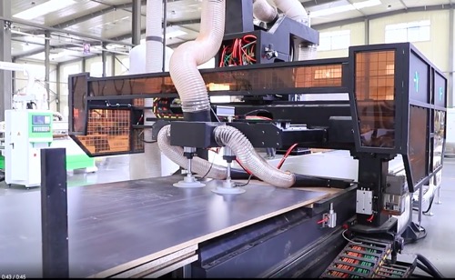
Bevel in plasma cutting is not a defect but a predictable physical outcome. The plasma arc, traveling at supersonic speeds, exits the nozzle with a slight angular divergence. As the arc penetrates the workpiece, the upper edge experiences more erosion than the lower edge, resulting in a cut face that is not perpendicular to the plate surface. This angular deviation typically ranges from 1° to 5°, depending on material thickness, cutting speed, amperage, and gas mixture.
The direction of bevel is consistent: the right side of the cut (when traveling forward) exhibits a positive angle, while the left side shows a negative angle. This asymmetry is inherent to the vortex stabilization of the plasma arc. Understanding this directionality is the first step toward effective compensation.
Mechanical Compensation Techniques
The most straightforward approach to achieving square cuts is mechanical compensation. This involves physically tilting the torch head to offset the natural bevel angle. On gantry-style plasma cutting machines, this is accomplished through a motorized torch rotator that adjusts the torch angle in real-time based on the cutting direction.
Torch Tilt Methodology:
- For clockwise cutting paths, the torch is tilted 1°–3° in the direction opposite to the natural bevel
- For counterclockwise paths, the tilt direction reverses
- The exact angle is determined by empirical testing on scrap material of the same grade and thickness
The limitation of mechanical compensation is that it requires a multi-axis torch head and sophisticated control logic. Machines equipped with basic single-axis torch holders cannot perform this adjustment dynamically.
Software-Based Bevel Compensation
Modern CNC controllers offer software-based compensation as an alternative or complement to mechanical tilting. This is achieved through path geometry modification: the controller adjusts the programmed toolpath to account for the expected bevel, effectively “pre-distorting” the cut geometry so that the resulting part meets dimensional specifications.
Key Parameters for Software Compensation:
| Parameter | Typical Range | Effect on Cut Quality |
|-----------|---------------|-----------------------|
| Kerf width | 0.5–2.5 mm | Determines material loss |
| Bevel angle | 1°–5° | Defines angular correction |
| Cutting speed | 500–6000 mm/min | Affects bevel severity |
| Torch height | 2–6 mm | Influences arc stability |
| Amperage | 30–400 A | Correlates with plate thickness |
The table above illustrates the critical variables that influence bevel formation. For a given material thickness, increasing cutting speed reduces the heat-affected zone but may exacerbate the bevel angle. Conversely, slower speeds allow more heat to penetrate, potentially reducing angular deviation but increasing dross formation.
Roctech® plasma cutting systems, such as those integrated into the gantry-style machines offered by Roctech Machinery Co., Ltd., incorporate advanced software compensation modules that automatically adjust these parameters based on material type and thickness. Their controllers can store profiles for common materials—carbon steel, stainless steel, aluminum—and recall the optimal compensation values with minimal operator intervention.
Torch Height Control (THC) and Its Role
Automatic torch height control is arguably the most critical subsystem for maintaining consistent cut quality. As the plasma arc cuts through the plate, the arc voltage fluctuates with changes in torch-to-work distance. A THC system continuously monitors this voltage and adjusts the Z-axis to maintain a constant standoff distance.
Improper THC settings directly contribute to bevel variation:
- Excessive torch height → wider kerf, increased bevel angle
- Insufficient torch height → narrow kerf, potential nozzle damage, inconsistent penetration
Modern THC systems, such as those found in Roctech’s plasma cutting machines, use predictive algorithms that anticipate voltage changes based on cutting speed and direction, rather than reacting after the fact. This proactive approach minimizes the oscillation that occurs with reactive THC systems and results in more uniform cut faces.
Practical Adjustment Procedure
The following step-by-step procedure is recommended for field adjustment of bevel compensation:
1. Prepare test coupons: Cut 100 mm × 100 mm squares from the same material grade and thickness as production parts.
2. Set baseline parameters
Looking for more information about our CNC machines and services? Contact us today.
Contact
Previous:Selecting the Correct Cutting Fluid for Machining Centers
Next:Heavy-Duty Machining Centers: Reshaping Industrial-Scale Wood and Stone Fabrication