
Aerospace Foam Mold Engraving: Precision CNC Solutions for Modern Tooling
About Us / Author:ROCTECH Engineer Team / Published: Sep 24 , 2026 / Last Updated: Sep 24 , 2026
The Role of CNC Foam Machining Centers in Aerospace Mold Fabrication
The aerospace industry's persistent demand for lightweight, complex geometries has elevated foam mold machining from a peripheral workshop activity to a critical path technology. Tooling for composite layup, prototype validation, and lost foam casting increasingly relies on large-format CNC engraving machines capable of maintaining dimensional integrity across expansive work envelopes. This article examines the technical and operational dimensions of aerospace foam mold engraving, with particular attention to the equipment configurations and processing strategies that define contemporary practice.
Industry Context and Equipment Requirements
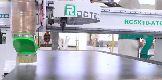
Aerospace foam molds serve multiple functions: they act as master patterns for composite layup tools, dimensional validation models for aerodynamic surfaces, and consumable patterns in lost foam casting processes. The materials involved—expanded polystyrene (EPS), extruded polystyrene (XPS), polyurethane tooling board, and syntactic foams—share common characteristics: low density, thermal sensitivity, and a tendency to generate fine dust during machining. These properties impose specific requirements on machine design, including high-speed spindle capability, effective dust extraction, and thermal stability of the machine structure itself.
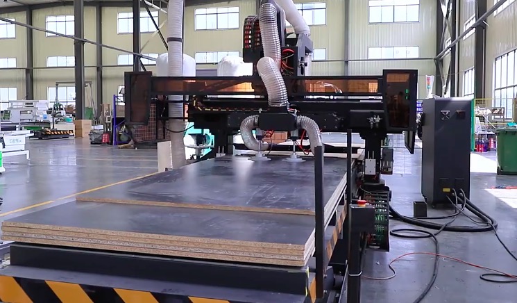
Unlike metal mold machining, foam processing does not demand extreme cutting forces. Instead, the priority shifts to rapid traversal across large volumes, smooth interpolation for compound curvature, and the ability to accommodate substantial workpiece dimensions. Aerospace applications frequently involve molds exceeding three meters in length, with some wing skin or fuselage section tools approaching six meters.
The table below compares representative machine configurations applicable to aerospace foam work, drawing on specifications typical of the Roctech product range and general industry data.
| Parameter | Standard Gantry Router | Heavy-Duty Foam Machining Center | Five-Axis Simultaneous Center |
|-----------|----------------------|----------------------------------|------------------------------|
| Typical Work Envelope (X×Y×Z) | 1300×2500×200mm | 2000×4000×800mm | 1300×2500×600mm |
| Spindle Power | 6–9 kW | 10–15 kW | 10 kW |
| Maximum Rapid Traverse | 30,000 mm/min | 45,000 mm/min | 30,000 mm/min |
| Positioning Accuracy | ±0.05 mm/300mm | ±0.05 mm/300mm | ±0.05 mm |
| Control System | Syntec / LNC | Syntec / OSAI | OSAI / Heidenhain |
| Drive Configuration | Servo (Yaskawa) | Servo (Yaskawa) | Servo (Yaskawa) |
| Typical Application | Small molds, patterns | Large fuselage/wing tools | Complex 3D contours |
The data reveals a clear trade-off between envelope size and dynamic performance. Heavy-duty configurations prioritize rigidity and travel length, often at the cost of acceleration. Five-axis simultaneous platforms, conversely, offer superior contouring capability but typically constrain workpiece size. For aerospace tooling, the selection hinges on the specific geometry: a wing leading edge mold with moderate curvature may favor a large three-axis gantry with a rotary axis attachment, whereas a complex engine nacelle tool demands full five-axis interpolation.
Technical Considerations in Foam Engraving
The machining of foam for aerospace tooling presents a distinct set of process parameters. Spindle speeds typically range from 12,000 to 24,000 RPM, with feed rates calibrated to avoid thermal degradation of the workpiece. Tooling generally consists of ball-end or bull-nose cutters, often coated with diamond-like carbon (DLC) to reduce wear and improve chip evacuation. The low density of foam means that chip clearance is rarely a problem, but the fine dust generated requires robust extraction—typically a combination of dust shoes and central collection systems.
Thermal management is another consideration. While foam is an excellent insulator, localized heating from friction can cause melting and dimensional distortion. This is particularly problematic in polyurethane tooling boards, which have a lower melting point than metal but higher than EPS. Operators often employ air blast cooling or reduce feed rates in areas of high curvature.
Accuracy verification for foam molds relies on coordinate measuring machines (CMMs) or portable laser trackers. Given the low stiffness of foam, contact measurement is generally avoided. Non-contact methods allow verification without risking deformation.
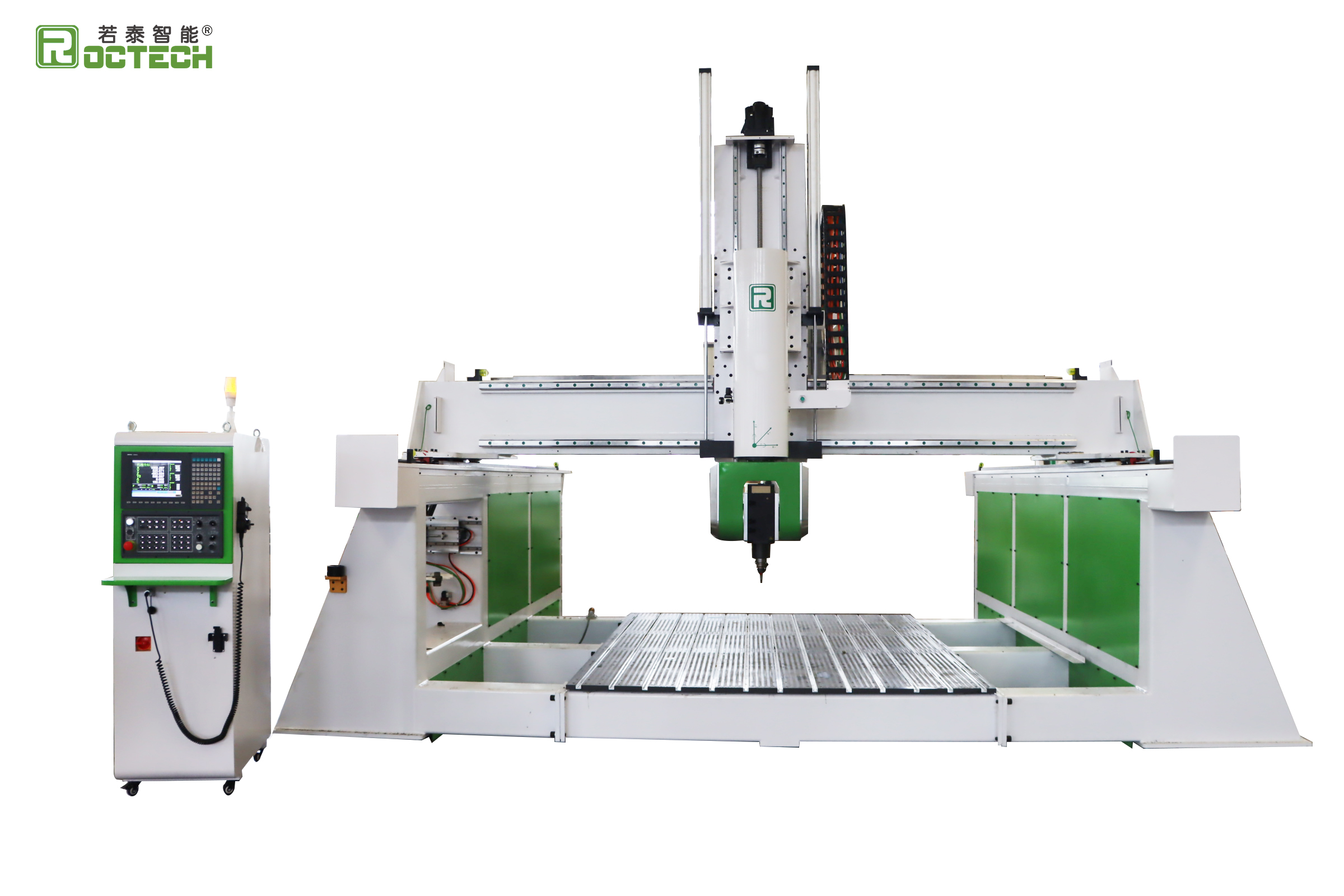
Roctech's EPS foam machining center series addresses several of these requirements directly. The machines feature large stroke designs suitable for the full-scale molds common in aerospace prototyping, with high-speed spindles and specialized dust collection. The availability of four-axis and five-axis linkage options enables the machining of compound curvature without repositioning, reducing setup error and improving surface continuity. For aerospace suppliers requiring traceable accuracy, the integration of imported servo systems and precision guide rails provides a baseline of repeatability that supports rigorous quality documentation.
Integration with Digital Workflows
Looking for more information about our CNC machines and services? Contact us today.
Contact
Previous:CNC滚齿机:精密齿轮加工的核心装备
Next:Not