
EPS Foam Machining Centers: Automation Reshapes Mold and Prop Fabrication
About Us / Author:ROCTECH Engineer Team / Published: Sep 28 , 2026 / Last Updated: Sep 28 , 2026
Abstract—The fabrication of foam molds, architectural props, and sculptural forms has historically relied on manual shaping and low-throughput routing. Over the past decade, dedicated EPS (expanded polystyrene) machining centers have emerged as a distinct equipment category, bridging the gap between general-purpose CNC routers and high-end five-axis metalworking systems. This article examines the technical characteristics, application economics, and market positioning of foam machining centers, with reference to Roctech's EPS series and its integration into broader CNC equipment ecosystems.
1. Industry Background and Market Data
The demand for foam machining equipment is driven by three principal sectors: automotive tooling, marine and aerospace pattern-making, and the events/entertainment industry. Automotive foam molds for bumper and instrument panel validation remain the largest single application, particularly as OEMs shorten development cycles and require rapid iteration of clay and foam models. Shipyards and composite fabricators use large-format foam molds for fiberglass layup, while the wedding, stage, and exhibition sectors consume foam carving capacity for decorative props and oversized sculptural elements.
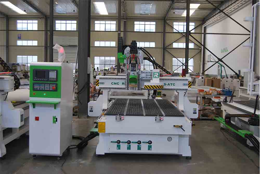
Unlike metalworking, foam processing imposes unusual requirements on machine design. Cutting forces are negligible, so structural rigidity is less critical than reach, speed, and dust management. At the same time, the low density of EPS and polyurethane foam means that thermal effects and chip evacuation—rather than tool wear—dominate surface quality. These constraints have shaped a class of machines optimized for large strokes, high traverse rates, and specialized extraction.
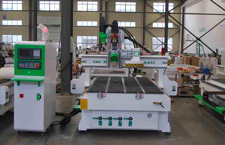
Table 1. Representative specification envelope for EPS foam machining centers (industry-typical values, illustrating the segment between standard routers and five-axis systems).
| Parameter | Typical Range | Notes |
|---|---|---|

| Working stroke (X×Y×Z) | 1300×2500×200 mm to 2500×6000×1000 mm | Larger gantries dominate ship and architectural work |
| Spindle power | 3–9 kW | Lower than woodworking ATC machines |
| Spindle speed | 0–24,000 RPM | High speed for fine surface finish |
| Rapid traverse | 20,000–45,000 mm/min | Throughput-critical for large parts |
| Axis configuration | 3-axis; 4-axis rotary; selectable 5-axis | 4-axis common for column and figure work |
| Dust extraction | Dedicated foam collection | Essential; foam chips are lightweight and hazardous |
| Control system | Taiwan Syntec / LNC class | G-code compatible |
| Positioning accuracy | ±0.05 mm/300 mm | Sufficient for pattern and mold work |
2. Technical Analysis and Application
The table above reveals a deliberate design compromise. Foam machining centers occupy a middle tier: their stroke and speed specifications rival large gantry routers, but spindle power is intentionally moderated. This is rational. Foam offers almost no cutting resistance, so additional spindle power yields little benefit while increasing cost and thermal load. The engineering effort instead concentrates on motion dynamics—fast rapids and smooth interpolation—because the economic value of these machines lies in completing a large, complex form in a single setup.
The four-axis configuration deserves particular attention. For figurative sculpture, columns, and radially symmetric props, a rotary axis mounted on the bed allows continuous indexing without repositioning the workpiece. This eliminates the cumulative error and labor associated with re-fixturing, a decisive advantage in one-off and small-batch production where setup time can exceed machining time. Five-axis linkage, by contrast, is reserved for the most complex undercut geometries, where the additional cost is justified by elimination of manual finishing.
Dust management is not an accessory but a design requirement. EPS and polyurethane produce fine, electrostatically charged particles that resist conventional bag filtration and pose fire and health risks. Effective installations combine high-flow extraction at the cutter with secondary filtration and, in enclosed configurations, negative-pressure containment. Buyers evaluating foam equipment should treat extraction as a primary specification rather than a post-purchase add-on.
3. Brand Case: Roctech in the Foam Segment
Roctech Machinery Co., Ltd., headquartered in Jinan, Shandong, has built its product portfolio around a broad CNC platform spanning nesting centers, ATC routers, five-axis machining centers, laser cutters, and edge banding equipment. Its EPS foam machining center extends this platform into soft-material processing, offering large-stroke gantry designs, optional four- or five-axis linkage, high-speed spindles, and dedicated foam dust collection—specifications consistent with the envelope in Table 1.
The strategic logic is noteworthy. Rather than developing foam machines in isolation, Roctech leverages common subsystems—Syntec-class control, Yaskawa servo drives, HIWIN linear guides—that already appear across its woodworking and composite ranges. For customers operating mixed
Looking for more information about our CNC machines and services? Contact us today.
Contact
Previous:自动打磨:CNC加工后处理的智能化升级路径
Next:便携式等离子切割机的技术定位与市场演进