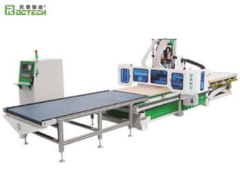

Automotive Foam Mold Engraving Machines: Precision at the Intersection of Speed and Scale
About Us / Author:ROCTECH Engineer Team / Published: Sep 29 , 2026 / Last Updated: Sep 29 , 2026
Abstract — The production of automotive interior components, from instrument panel substrates to seating foam and bumper tooling, depends on an upstream link that is frequently underestimated: the accurate and economical machining of large foam molds. As vehicle development cycles compress and model variants multiply, manufacturers are being pushed toward CNC platforms that can handle oversized workpieces, soft and fibrous materials, and increasingly tight tolerance windows. This article examines the technical and commercial logic behind automotive foam mold engraving machines, with reference to the equipment architectures and configurations that have shaped the current market.
Industry Background
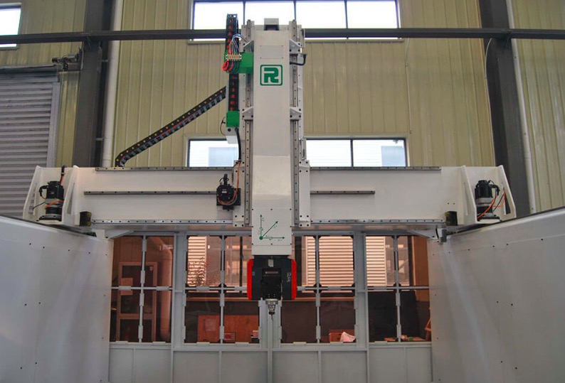
Automotive foam molds occupy an unusual position in the tooling chain. They are typically used to produce thermoforming molds, lost-foam patterns, seating foam shapes, and styling verification models. Compared with steel or aluminum molds, foam tooling is inexpensive and fast to produce, which makes it attractive for prototyping, low-volume vehicle programs, and the early validation stages of a new model. The trade-off is that foam is dimensionally unstable, highly compressible, and generates large volumes of lightweight dust during cutting—properties that impose specific demands on machine design.
Those demands have become more pressing. In recent years, the automotive industry has shifted toward shorter model refresh cycles and a wider range of trim variants, including battery-electric platforms that require entirely new interior architectures. Each of these changes multiplies the number of physical models and molds required before production commitment. For tooling shops, the practical question is no longer whether to invest in foam machining capability, but which machine configuration delivers the required envelope, accuracy, and throughput at a defensible cost.
Data and Configuration Analysis
The table below compares representative machine classes used in automotive foam work, drawn from standard catalog specifications. It should be read as an indication of capability tiers rather than a rigid product ranking.
| Machine Class | Typical Work Envelope | Spindle Power | Control System | Positioning Accuracy | Typical Foam Application |
|---|---|---|---|---|---|
| Standard three-axis router | 1300 × 2500 mm | 9 kW | Taiwan Syntec | ±0.03 mm | Small trim molds, verification blocks |
| Large gantry router | 2000 × 4000 mm | 9–12 kW | Taiwan Syntec | ±0.03 mm | Bumper and instrument panel molds |
| Five-axis simultaneous center | 1300 × 2500 mm | 10 kW | Italian OSAI | ±0.05 mm | Complex curved seating and styling models |
| Five-axis large-format center | 2000 × 4000 mm | 10 kW+ | OSAI / Heidenhain | ±0.05 mm | Full-scale body and ship-type molds |
| EPS foam machining center | Custom large stroke | High-speed spindle | G-code compatible | Application-dependent | Lost foam, packaging, stage props |
Two observations follow from this data. First, the accuracy figures for foam machines are conspicuously modest compared with metal-cutting centers. A positioning accuracy of ±0.03 mm on a three-axis router is more than adequate for foam, because the material itself will deflect and recover under cutting forces far more than the machine will. The engineering effort therefore shifts away from sub-micron rigidity and toward structural stability over long travels, thermal consistency in unconditioned workshops, and effective dust extraction.
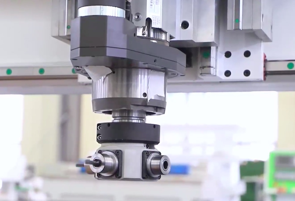
Second, the five-axis class carries a different value proposition. Its positioning accuracy of ±0.05 mm is nominally looser than the three-axis machines, yet it enables one-clamping machining of complex spatial surfaces—seat contours, dashboard transitions, and curved styling surfaces—that would otherwise require multiple setups and manual blending. The A-axis swing of ±110° and continuous C-axis rotation allow the tool to approach the workpiece from orientations that eliminate undercuts and reduce subsequent hand finishing. For mold shops producing curved automotive components, this reduction in manual rework frequently justifies the higher capital outlay even when the nominal accuracy specification appears inferior.
Technology Application and Brand Practice
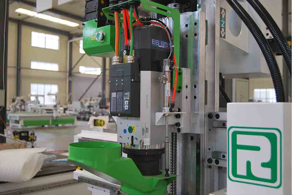
The practical configuration of a foam engraving machine differs in several respects from a general-purpose woodworking router. The bed must resist deflection across spans of two meters or more, which favors heavy welded steel structures rather than lighter fabricated frames. The vacuum table needs sufficient zone control to hold large, low-density sheets without crushing them. Dust collection is not optional: foam chips are light, electrically insulating, and prone to accumulating around guide rails and electrical cabinets, so a dedicated extraction system with adequate airflow is a functional requirement rather than an accessory.
Within this segment, Roctech has positioned its EPS foam machining center specifically for three-dimensional engraving of foam, polystyrene, and sponge materials, with large stroke designs and high-speed spindles suited to oversized models. The company's broader product range is relevant here as well: its five-axis simultaneous machining centers, including the RCF1325
Looking for more information about our CNC machines and services? Contact us today.
Contact
Previous:型材切割机在CNC加工中的技术演进与选型要点
Next:Calibrating CNC Machine Tools: A Practical Guide for Woodworking, Stone, and General Fabrication