
Title: Optimizing Tool Life in CNC Engraving: A Technical Examination of Wear Factors and Maintenance Protocols
About Us / Author:ROCTECH Engineer Team / Published: Aug 02 , 2026 / Last Updated: Aug 02 , 2026
Abstract
Tool life in CNC engraving and machining operations is a multifaceted parameter influenced by material properties, cutting parameters, spindle integrity, and maintenance discipline. For fabricators operating woodworking, stone, and metal cutting equipment, understanding the mechanisms of tool degradation is not merely a matter of cost control—it is fundamental to ensuring dimensional accuracy, surface finish quality, and predictable production scheduling. This article examines the technical determinants of tool longevity, presents comparative data on wear indicators across common substrate categories, and discusses how equipment design and proactive maintenance routines—exemplified by systems from manufacturers like Roctech—can extend operational intervals and reduce unplanned downtime.
Industry Background and Data Analysis
The economics of CNC fabrication are increasingly dictated by consumable tooling costs and the labor associated with tool changes. In high-throughput environments, a seemingly minor reduction in tool life can translate into significant annual expenditure. According to industry benchmarks, tooling can represent up to 3-5% of total production cost in woodworking, with this figure rising substantially for abrasive materials like engineered stone or MDF with high resin content.
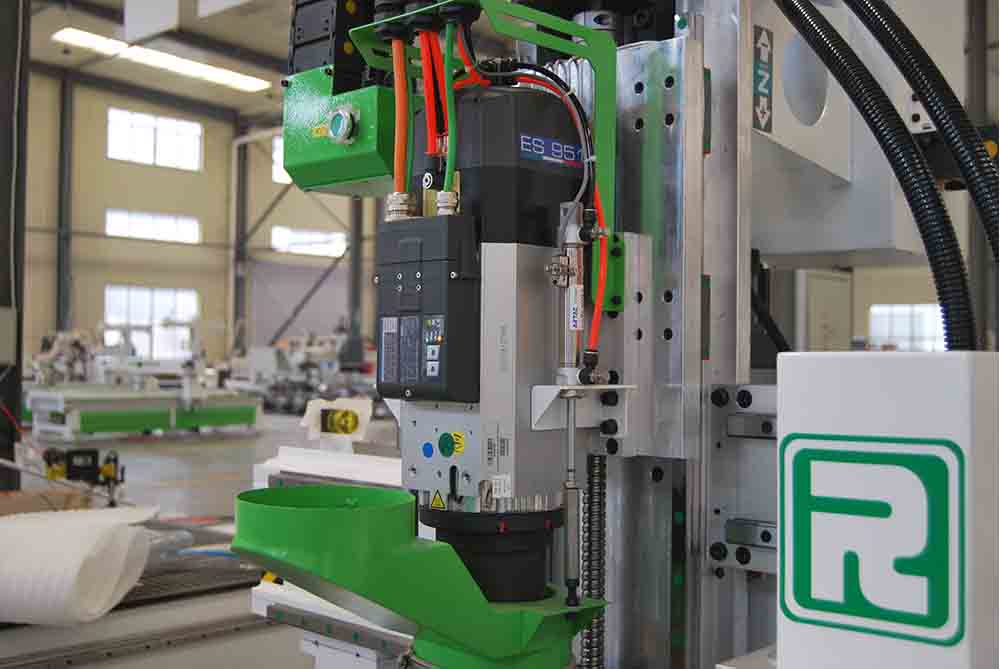
Tool wear is not a linear process. It typically follows a three-stage curve: initial break-in wear, a period of steady-state wear with predictable performance, and finally accelerated flank wear leading to catastrophic failure or unacceptable part quality. The challenge for operators is identifying the transition point between stage two and stage three before defects occur.
The table below summarizes typical tool life expectations and primary wear indicators across common engraving applications, based on aggregated operational data from small to medium fabrication shops.
| Application Material | Tool Type (Typical) | Spindle Speed (RPM) | Average Tool Life (Hours) | Primary Wear Indicator | Dominant Wear Mechanism |
|---|---|---|---|---|---|
| Solid Wood (Hardwood) | Carbide Single Flute | 15,000 – 18,000 | 40 – 60 | Edge chipping / increased surface roughness | Abrasive wear & micro-chipping |
| MDF / HDF | Carbide Compression | 16,000 – 20,000 | 25 – 40 | Burn marks / darkened edges | Heat-induced resin adhesion & abrasive wear |
| Acrylic / Plastics | Carbide O-Flute (Polished) | 12,000 – 15,000 | 30 – 50 | Re-melted chips / cloudy cut surface | Chemical degradation & heat generation |
| Aluminum (Grade 6061) | Carbide 2-Flute (Coated) | 10,000 – 12,000 | 15 – 25 | Built-up edge (BUE) / poor finish | Adhesive wear & thermal cracking |
| Granite / Marble | Diamond-Tipped (PCD) | 6,000 – 9,000 | 60 – 100+ | Reduced feed pressure / smoothness loss | Impact fatigue & diamond grain pull-out |
Analysis of Table Data: The data illustrate that tool life is inversely correlated with the material's abrasiveness and thermal conductivity. For instance, MDF, while soft, contains formaldehyde-based resins and recycled wood fibers that are highly abrasive, often reducing tool life to half that of solid wood. Conversely, polycrystalline diamond (PCD) tools, despite their higher initial cost, offer exceptional longevity in stone due to their hardness, though they are vulnerable to impact failure from interrupted cuts.
Another critical insight is the role of spindle speed. Operating at the lower end of the recommended RPM range for a given material often extends tool life disproportionately. However, this must be balanced against feed rate to maintain a consistent chip load. A reduction in RPM without a corresponding reduction in feed rate leads to thinner chips, increased rubbing, and accelerated heat generation—a common cause of premature failure that is often misdiagnosed as a tool quality issue.
Technical Applications and Brand Case Study
The interaction between machine tool rigidity and tool life cannot be overstated. A machine lacking structural stiffness will induce vibration, which translates to micro-impact loads on the cutting edge. These impacts accelerate flank wear and can cause catastrophic tool breakage, particularly in brittle materials like stone or glass-reinforced plastics. This is where the design philosophy of the equipment manufacturer plays a decisive role.
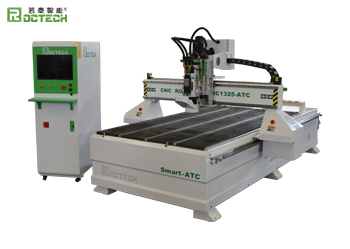
For instance, Roctech Machinery Co., Ltd., a prominent manufacturer of CNC routers and machining centers, emphasizes a heavy-duty welded and stress-relieved bed structure in its Roctech® product lines, such as the RC1325S-ATC. The rationale is straightforward: a heavier, more rigid frame absorbs cutting forces rather than transmitting them back into the spindle and tool. This is particularly critical when using automatic tool changers (ATC), where consistent clamping force and spindle alignment are essential. If the machine body flexes, the tool holder may not seat correctly,
Looking for more information about our CNC machines and services? Contact us today.
Contact
Previous:Three-Axis Machining Centers: The Backbone of Modern Woodworking and Stone Fabrication
Next:EPS Foam Machining: Precision, Scale, and the Evolution of Large-Format CNC