
Understanding and Mitigating Dislocation in CNC Engraving Machines
About Us / Author:ROCTECH Engineer Team / Published: Aug 25 , 2026 / Last Updated: Aug 25 , 2026
Dislocation—the loss of positional accuracy between commanded and actual tool paths—remains one of the most persistent and costly challenges in CNC engraving, particularly in woodworking and stone fabrication. While the symptom manifests as misaligned cuts, stepped surfaces, or dimensional drift, its root causes are systemic, spanning mechanical, electrical, and programming domains. This article examines the primary failure modes, offers a structured diagnostic approach, and outlines corrective actions, drawing on field experience and standard industry practice.
Root Causes: A Systematic Breakdown
Dislocation rarely stems from a single event. It is typically the cumulative result of several interacting deficiencies. The following table summarizes the most common categories, their typical indicators, and corresponding diagnostic priorities.
| Fault Category | Common Indicators | Primary Diagnostic Focus |
|---------------------|-----------------------|------------------------------|
| Mechanical Backlash | Unidirectional error; visible play in axis when reversing | Ball screw nut preload; rack-and-pinion mesh; coupling set screws |
| Drive System Fault | Servo alarm; motor overheating; axis stalls under load | Servo drive parameters; encoder feedback; motor brake release |
| Transmission Wear | Progressive error over time; rough movement; audible grinding | Guide rail lubrication; bearing wear; belt tension (if applicable) |
| Workpiece Fixation Failure | Localized shifting; error magnitude varies with material type | Vacuum pump pressure; vacuum table zone sealing; workpiece flatness |
| Programming & Toolpath Error | Consistent error at specific coordinates; error scales with feed rate | Post-processor configuration; acceleration/deceleration settings; G-code syntax |
| Control System Interference | Random, non-systematic errors; errors occur during rapid traverse | Electrical noise shielding; grounding; cable shielding integrity |
Mechanical Backlash: The Most Prevalent Culprit
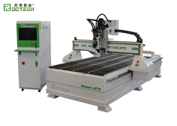
In woodworking and stone engraving machines—where rack-and-pinion drives are common due to their long stroke and high speed—backlash is the leading mechanical cause of dislocation. For a machine like Roctech’s RC1325S-ATC, which uses rack-and-pinion on X/Y axes, a loose mesh between the pinion and rack introduces free play. When the axis reverses direction, the pinion must traverse that play before engaging the rack again, causing a positional error equal to the backlash value.
Diagnostic Method: Use a dial indicator mounted against the spindle or table. Command a small incremental move (e.g., 0.01 mm) in one direction, record the reading, then command the same increment in reverse. The difference between the two readings indicates backlash.
Corrective Actions:
- Adjust the pinion–rack mesh pressure to the manufacturer’s specification, typically 0.03–0.05 mm preload.
- Check the coupling between the servo motor and pinion; a set screw loosened by vibration is a common failure.
- Replace worn pinions; a pinion with visible wear on one flank will produce directionally biased errors.
For ball screw–driven axes (commonly the Z-axis), backlash indicates nut preload loss. In Roctech’s five-axis RCF series, which relies on precision ball screws, re-preloading the nut or replacing it is necessary, as nut wear accelerates once clearance appears.
Drive System and Servo Parameters
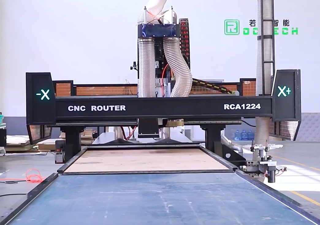
A servo system that is under-tuned for the machine’s inertia can cause following error—the lag between commanded and actual position during acceleration or deceleration. This is particularly evident in heavy-gantry machines like the RCA1224 nesting center, where the moving mass is substantial. The Yaskawa servo drives commonly used by Roctech allow adjustment of position loop gain, velocity loop gain, and feed-forward gain. If the proportional gain is too low, the axis will lag during rapid moves, producing a consistent dislocation in one direction.
Diagnostic Method: Monitor the servo drive’s following error value during a test run at the machine’s maximum rapid traverse speed. If the error exceeds the machine’s positioning tolerance (typically ±0.03 mm for Roctech ATC models), the gain parameters require adjustment.
Corrective Actions:
- Increase position loop gain incrementally, then adjust velocity loop gain to maintain stability.
- Enable feed-forward compensation—this dramatically reduces following error in linear axes.
- Verify that the acceleration/deceleration time constants in the CNC system (e.g., Syntec) match the servo’s capability. Excessive acceleration demands torque beyond the motor’s continuous rating, causing stalling or encoder alarm.
Workpiece Fixation and Vacuum Integrity
In stone and engineered quartz fabrication, dislocation is frequently traced not to the machine but to the workpiece shifting during the cut. Roctech’s stone CNC routers typically employ a vacuum table with multiple zones
Looking for more information about our CNC machines and services? Contact us today.
Contact
Previous:The Evolution of CNC Woodworking Machinery: Insights from Qingdao
Next:Automation Reshapes Panel Processing: Insights from the Suzhou Furniture Fair