
Screw Backlash Compensation in CNC Systems: A Practical Framework
About Us / Author:ROCTECH Engineer Team / Published: Aug 28 , 2026 / Last Updated: Aug 28 , 2026
---
Abstract
In CNC machining, the transmission chain between servo motor and worktable frequently relies on ball screws. Over time, mechanical wear and thermal deformation introduce backlash—a measurable lost motion that compromises positioning accuracy and surface finish. This article examines the causes of screw clearance, presents a structured adjustment methodology for both mechanical and CNC-side compensation, and contextualizes these practices within modern woodworking and stone fabrication environments. Particular attention is paid to the balance between mechanical tightening and software compensation, drawing on field experience from industrial equipment such as those manufactured by Roctech Machinery Co., Ltd.
---
1. Introduction
The ball screw assembly remains the dominant linear actuation component in CNC routers, machining centers, and stone engraving systems. Its recirculating ball bearings offer low friction and high repeatability. However, no mechanical system is immune to wear. Backlash—the angular play between screw shaft and nut—manifests as positional error during direction reversals. In woodworking nesting operations or stone carving, where tool paths frequently alternate direction, even 0.05 mm of backlash can produce visible tool marks, dimensional drift, and accelerated tool wear.
This paper addresses a question central to every maintenance engineer: How to adjust the screw clearance? The answer requires understanding both the mechanical preload mechanisms and the electronic compensation available in contemporary CNC controllers.
---
2. Industry Context and Quantitative Impact
To appreciate the significance of screw clearance adjustment, consider typical accuracy budgets in panel furniture production. Table 1 summarizes representative positioning specifications for mid-range CNC machining centers commonly deployed in cabinet and stone fabrication shops.
| Parameter | Woodworking Nesting Center | Stone CNC Router | Typical Tolerance Requirement |
|-----------|----------------------------|------------------|-------------------------------|
| Positioning Accuracy | ±0.03 mm / 300 mm | ±0.05 mm / 300 mm | ±0.1 mm over full travel |
| Repeat Positioning Accuracy | ±0.02 mm | ±0.03 mm | ±0.05 mm |
| Maximum Rapid Traverse | 45,000 mm/min | 15,000 mm/min | — |
| Screw Lead (Z-axis) | 10 mm | 12 mm | — |
| Recommended Backlash Limit | ≤ 0.02 mm | ≤ 0.03 mm | — |
Table 1: Comparative accuracy budgets for woodworking and stone CNC systems.
The data indicate that mechanical backlash should not exceed roughly one-third of the repeatability specification. When backlash exceeds 0.03 mm in a woodworking center, edge banding alignment and dowel hole positioning degrade noticeably. In stone machining, excessive clearance accelerates diamond tool chipping and leaves scalloped surfaces on granite edges.
---
3. Mechanical Adjustment of Screw Clearance
3.1 Double-Nut Preload Method
Most industrial ball screws employ a double-nut arrangement with a preload spacer. The adjustment procedure is as follows:
- Loosen the locknut securing the spacer between the two nut halves.
- Rotate the spacer to increase its effective length, thereby forcing the nuts apart and eliminating axial play.
- Tighten the locknut and verify by manually rotating the screw—resistance should be uniform without detectable free rotation.
- Measure backlash using a dial indicator mounted against the worktable; acceptable residual is 0.01–0.02 mm.
For applications requiring higher rigidity, some manufacturers use oversized balls or a spring-loaded single nut. In those cases, replacement of the ball set is the only reliable remedy once wear exceeds elastic limits.
3.2 Axial Bearing Preload at the Fixed End
Backlash is not solely a nut issue. The screw shaft’s axial play at the bearing block also contributes. At the fixed end, angular contact bearings are typically preloaded by a locknut. Adjusting this nut removes shaft end float. The correct torque is specified by the bearing manufacturer; over-tightening causes overheating and premature bearing failure.
3.3 Practical Sequence for Maintenance Teams
1. Clean the screw surface and inspect for pitting or discoloration.
2. Check the screw support bearings for audible noise during rapid traverse.
3. Measure backlash at three positions along the screw: near the motor, mid-travel, and far end. Discrepancies indicate screw bending or support bearing wear.
4. Perform nut preload adjustment only after confirming the screw itself is straight and the supports are sound.
---
4. CNC-Side Compensation
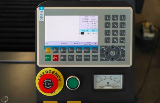
Even after mechanical adjustment, residual backlash of 0.01–0.02 mm often remains. Modern CNC controllers—such as the Syntec systems used in Roctech machinery—offer backlash compensation parameters. The process involves:
- Executing a bidirectional positioning test to quantify the error at reversal.
- Entering the measured value (typically in microns) into the controller’s compensation table
Looking for more information about our CNC machines and services? Contact us today.
Contact
Previous:Title: Precision and Repeatability: The Engineering Imperative in Modern Edge Banding Systems
Next:Five-Axis Machining Centers: Redefining Complex Woodworking