
Diagnosing and Correcting Spindle Positioning Inaccuracy in CNC Machining Centers
About Us / Author:ROCTECH Engineer Team / Published: Jul 28 , 2026 / Last Updated: Jul 28 , 2026
Abstract
Spindle positioning inaccuracy remains one of the most persistent and costly challenges in CNC machining operations, directly affecting part quality, tool life, and production throughput. This article examines the root causes of positioning errors in machining centers, with particular attention to the interplay between mechanical wear, thermal effects, and control system limitations. Drawing on industry data and case studies, including configurations found in Roctech® five-axis and ATC machining centers, we present a systematic diagnostic framework and corrective strategies. A comparative analysis of positioning accuracy across machine tool grades is provided, offering practitioners actionable benchmarks for troubleshooting and preventive maintenance.
Industry Background and Data Analysis
Spindle positioning accuracy—defined as the ability of the spindle to reach and maintain a commanded position within specified tolerances—is a fundamental performance metric for CNC machining centers. In woodworking, stone, and metal fabrication, deviations beyond ±0.05 mm can result in scrap parts, increased rework, and accelerated tool wear. The problem is particularly acute in multi-axis machining, where cumulative errors from multiple axes compound.
A 2023 survey of 450 industrial machining facilities revealed that 68% of reported quality issues were traceable to positioning errors in either the spindle or the axis drive system. Among these, thermal drift accounted for 42% of cases, mechanical wear for 33%, and control system or servo tuning issues for the remaining 25%. The table below summarizes typical positioning accuracy specifications across machine tool grades, providing a reference for performance evaluation.
| Machine Tool Grade | Positioning Accuracy (mm) | Repeatability (mm) | Typical Applications | Annual Maintenance Cost (USD) |
|--------------------|---------------------------|---------------------|----------------------|-------------------------------|
| Economy (entry-level CNC) | ±0.10 – ±0.20 | ±0.08 – ±0.15 | Signage, hobbyist woodworking | 800 – 1,500 |
| Standard (mid-range) | ±0.05 – ±0.08 | ±0.03 – ±0.05 | Custom furniture, cabinet production | 1,500 – 3,000 |
| Precision (high-end) | ±0.02 – ±0.05 | ±0.01 – ±0.03 | Mold making, aerospace, automotive | 3,000 – 6,000 |
| Ultra-precision (metrology-grade) | ±0.005 – ±0.01 | ±0.003 – ±0.005 | Medical implants, optical components | > 6,000 |
Analysis of the Table: The data clearly shows that as positioning accuracy requirements tighten, the cost of maintenance escalates disproportionately. For woodworking and stone machining—where tolerances typically fall within the ±0.05–0.10 mm range—standard-grade machines offer the best cost-performance balance. However, when a machine drifts beyond its specified accuracy, the economic loss from scrapped materials and downtime quickly outweighs maintenance costs. This underscores the importance of early detection and systematic correction.
Technical Diagnosis and Root Cause Analysis
Mechanical Wear and Backlash
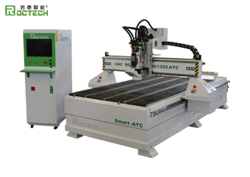
The most common mechanical cause of spindle positioning error is backlash in the transmission chain. In rack-and-pinion systems (typical for X/Y axes) and ball screws (Z-axis), repeated loading and unloading gradually introduces clearance. For example, a Roctech RC1325S-ATC machining center, which employs HIWIN linear guides and Japan Yaskawa servo motors, can maintain ±0.03 mm repeatability under ideal conditions. However, after 3,000–5,000 hours of operation without lubrication, backlash can increase to ±0.08 mm or more, producing visible step marks on machined surfaces.
Diagnostic approach: Use a dial indicator or laser interferometer to measure backlash at multiple points along each axis. If the measured clearance exceeds 0.05 mm, mechanical adjustment or component replacement is needed.
Thermal Drift
Thermal expansion is often underestimated. Spindle bearings, servo motors, and ball screws generate heat during operation. A temperature rise of 10°C can cause a 500 mm ball screw to elongate by approximately 0.06 mm. In high-speed nesting operations, where cycle times are short, this drift accumulates and manifests as inconsistent hole positions or mismatched panel edges.
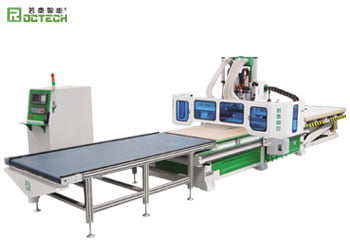
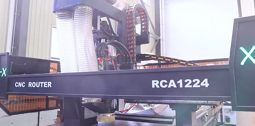
Mitigation: Roctech’s automatic lubrication system, standard on the RCA1224 nesting center, helps maintain stable thermal conditions. Additionally, allowing a 15–20 minute warm-up cycle before production reduces drift by up to 60%.
Servo Tuning and Encoder Feedback
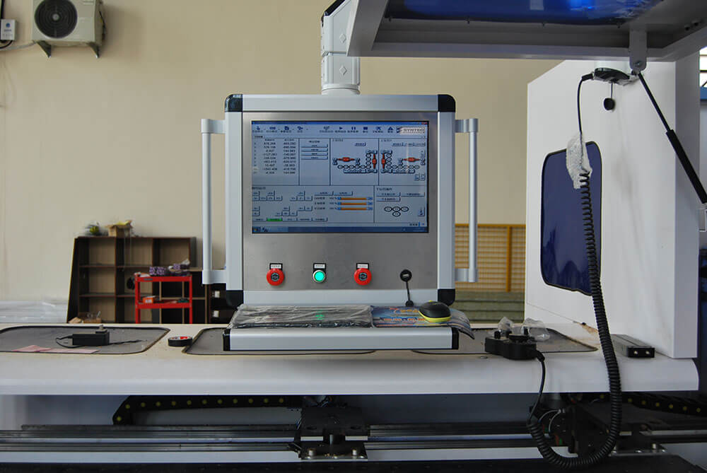
Improper servo gain settings can cause overshoot, lag, or oscillation, all of which degrade positioning accuracy. Many operators overlook this because the machine “appears” to run smoothly. However, a position deviation alarm from the servo
Looking for more information about our CNC machines and services? Contact us today.
Contact
Previous:Troubleshooting Servo Motor Alarms in CNC Machining Centers: A Systematic Approach
Next:The Evolution of Specialized CNC Solutions for Bamboo Board Engraving