
Restoring Lost Precision: A Systematic Approach to CNC Engraving Machine Accuracy Decline
About Us / Author:ROCTECH Engineer Team / Published: Sep 01 , 2026 / Last Updated: Sep 01 , 2026
CNC engraving machines, like all precision electromechanical systems, are subject to progressive accuracy degradation over their operational lifespan. This decline is rarely sudden; it manifests as subtle dimensional drift, deteriorating surface finish, or audible irregularities during cutting. For fabricators relying on woodworking, stone, or non-ferrous metal engraving, the economic consequences of unrecognized accuracy loss compound quickly—scrapped material, rework labor, and compromised delivery schedules. This article outlines a structured diagnostic methodology for identifying and rectifying accuracy degradation in CNC engraving equipment, drawing on established mechanical and control-system principles.
The Nature of Accuracy Decline
Accuracy in a CNC engraving machine is a composite property, integrating geometric precision (straightness, squareness, parallelism), positioning repeatability, and dynamic rigidity. The knowledge base for Roctech products—a manufacturer whose ATC series and five-axis machining centers are widely deployed in furniture and mold industries—indicates that positioning accuracy specifications typically range from ±0.03 mm to ±0.05 mm, with repeatability at similar magnitudes. When these figures deteriorate beyond acceptable thresholds, the root cause is rarely a single component failure. Rather, it is the cumulative effect of wear, contamination, thermal distortion, and mechanical loosening.
The first step in any accuracy restoration protocol is quantification. Operators should perform a standard ball-bar or laser interferometer test, or, at minimum, a rigorous dial-indicator check across each axis's travel. Documenting the actual deviation pattern—whether it is unidirectional backlash, periodic error, or non-linear drift—provides the essential clue for targeted intervention.

Mechanical Transmission: The Primary Suspect
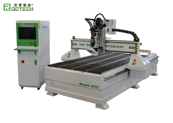
The most frequent source of positioning error in engraving machines is the transmission system. In the Roctech RC1325S-ATC model, the X and Y axes employ rack-and-pinion drives, while the Z axis uses a ball screw. Rack-and-pinion systems are inherently susceptible to backlash—the clearance between mating gear teeth—which manifests as lost motion when the axis reverses direction. Over time, pinion wear and mounting bracket loosening increase this clearance. The remedy involves two steps: first, mechanically re-tensioning the pinion against the rack to eliminate play; second, applying the control system's backlash compensation parameter. Syntec and LNC controllers, commonly fitted on Roctech machines, offer dedicated compensation registers for each axis.
Ball screws, conversely, suffer from preload loss. A properly preloaded nut eliminates axial play, but after extended duty cycles, ball wear reduces this preload. The symptom is a characteristic "clunk" during direction changes and a measurable dead zone in positioning. Replacing the nut assembly is the definitive solution, though temporary improvement can be achieved through careful adjustment of the nut's preload mechanism, provided the screw itself is not worn to a "hourglass" profile.
Guide rails, particularly the linear guides from HIWIN or PMI used in Roctech equipment, also contribute to accuracy decline when contaminated. Abrasive dust—common in wood and stone processing—enters the carriage seals and accelerates ball wear. A simple yet effective maintenance step is flushing the guide carriages with appropriate solvent and re-greasing with a lithium-based or manufacturer-specified lubricant. If the carriage exhibits rough movement or audible grinding, replacement is necessary; attempting to "run in" a damaged carriage will only damage the rail itself.
Spindle and Tooling Influences
The spindle's radial runout directly transfers to the cutting tool, producing oversized slots, tapered holes, and poor surface finish. For machines equipped with ER32 collets, as specified for Roctech's ATC series, runout typically originates from a worn collet or a contaminated taper seat. A dial indicator check on the collet taper, rotating the spindle by hand, will reveal runout in excess of 0.01 mm. Replacing the collet, cleaning the taper with a non-linting cloth, and re-torquing the collet nut with a torque wrench is a low-cost, high-impact correction. For machines with automatic tool changers, a misaligned tool magazine can also cause repeated off-center tool seating, leading to inconsistent cutting geometry.
Spindle bearing wear is a more severe issue. As bearings degrade, the spindle shaft develops axial and radial play, causing chatter and aggressive tool wear. While spindle rebuild is a specialized task, operators can monitor bearing health through vibration analysis or by listening for a high-frequency whine during deceleration. Roctech's specification allows for spindle speeds up to 24,000 RPM; operating continuously at maximum speed without adequate warm-up accelerates bearing wear. Instituting a five-minute warm-up cycle at 50% speed is a preventive practice that extends spindle life considerably.
Control System and Servo Loop T
Looking for more information about our CNC machines and services? Contact us today.
Contact
Previous:CNC Programming: A Strategic Skill for the Automated Shop Floor
Next:The Role of Automatic Labeling in Modern CNC Panel Processing Workflows