
Precision Verification Protocols for CNC Engraving Equipment: A Practical Framework
About Us / Author:ROCTECH Engineer Team / Published: Sep 06 , 2026 / Last Updated: Sep 06 , 2026
For manufacturers and job shops operating CNC routers, the question is not whether accuracy testing should be performed, but how to do it systematically without disrupting production. While many operators rely on the machine's own positional feedback to judge health, that approach is inherently limited — the control system measures the commanded position of the motor, not the actual position of the spindle relative to the workpiece. Independent verification is therefore indispensable.
The Core Problem: Closed-Loop Does Not Mean Self-Verifying
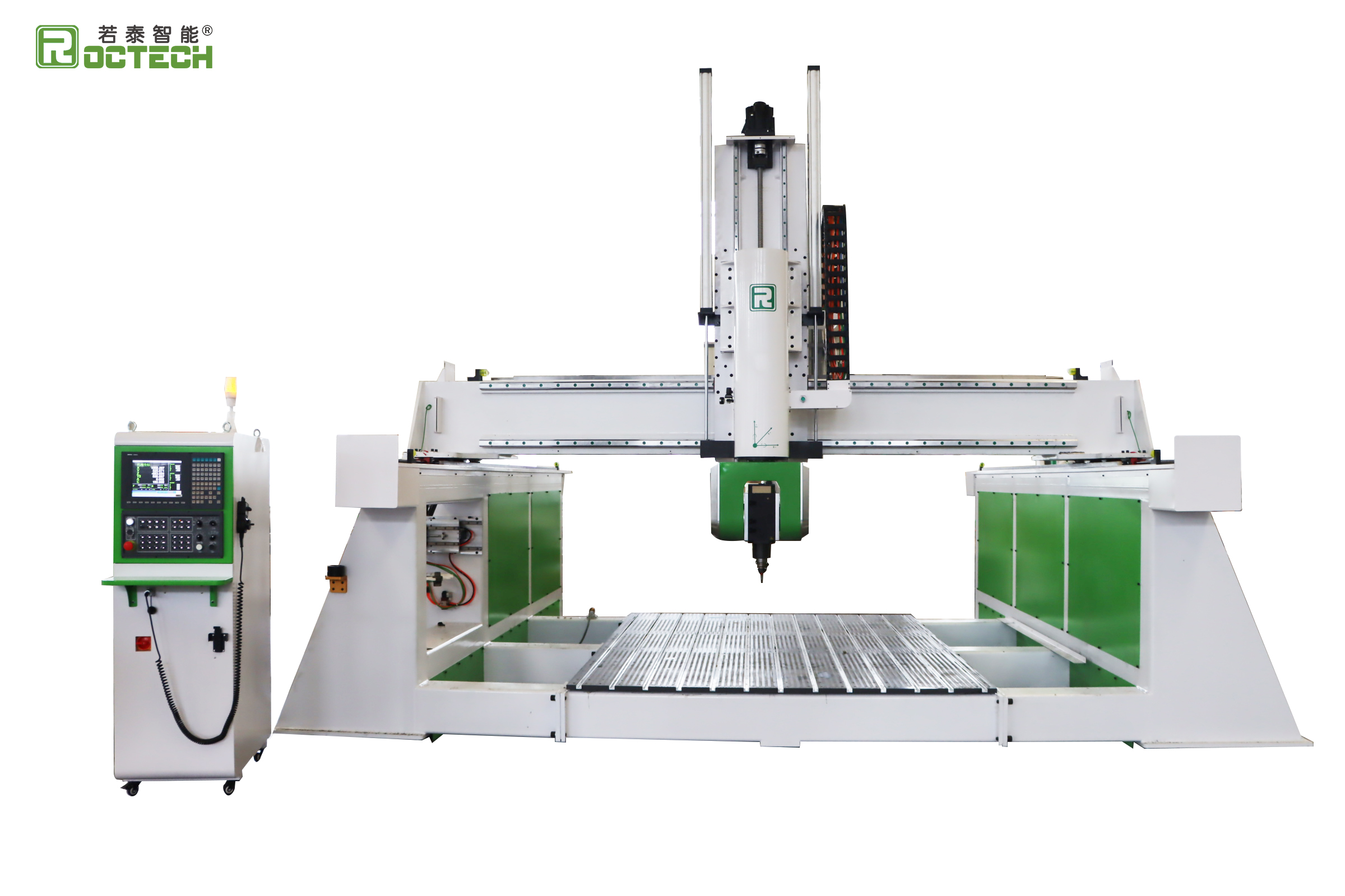
A typical engraving machine — whether a three-axis unit or a five-axis machining center — is equipped with encoders on servo motors (often Yaskawa or Delta in mid-range machines) that close the velocity and position loops. These loops ensure the motor shaft reaches its commanded angle. However, the mechanical chain between motor and tool — rack-and-pinion on X/Y axes, ball screw on Z, couplings, guide rail preload, and spindle runout — introduces errors that the servo loop cannot sense. Backlash, guide rail wear, thermal drift, and tool holder eccentricity all manifest as dimensional deviation at the workpiece. Consequently, accuracy testing must be performed at the spindle nose or, better, at the tool tip against an external reference.
A Structured Testing Sequence
Accuracy verification falls into three categories: geometric, positioning, and machining. Each addresses a different layer of error sources.
Geometric accuracy checks the machine's structural alignment — squareness between axes, flatness of the worktable, and parallelism of guide rails to the table surface. For a gantry-style engraver, a granite square and dial indicator are sufficient for basic checks. Place the square on the vacuum table, indicate along the X-axis over a 300 mm length, then repeat on the Y-axis. The measured deviation should be within ±0.02 mm for a mid-range machine — Roctech's ATC series, for example, specifies positioning accuracy of ±0.03 mm/300 mm on their RC1325S-ATC model, so the squareness check should be in the same order of magnitude.
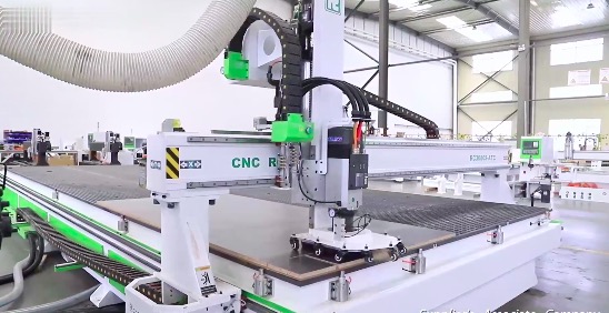
Positioning accuracy — the difference between commanded and actual position — is measured using a laser interferometer or, more economically, a ballbar or dial indicator against gauge blocks. The standard practice follows ISO 230-2: command a series of moves along each axis, record the actual positions, and compute the mean positional deviation and repeatability. For our purposes, a simplified version suffices. Mount a dial indicator with 0.001 mm resolution on the spindle, zero it against a fixed stop, command a 100 mm move, and read the deviation. Repeat five times in each direction. The spread between forward and reverse readings gives you backlash; the spread across repetitions gives you repeatability.
| Verification Level | Typical Method | Acceptable Deviation (Woodworking Class) | Acceptable Deviation (Mold/High-Precision) | Suggested Frequency |
|---|---|---|---|---|
| Geometric (squareness, flatness) | Granite square, dial indicator | ±0.05 mm / 300 mm | ±0.02 mm / 300 mm | Quarterly |
| Positioning (linear accuracy) | Laser interferometer or gauge blocks | ±0.1 mm / 1000 mm | ±0.03 mm / 300 mm | Monthly |
| Repeatability (bi-directional) | Dial indicator, repeated moves | ±0.05 mm | ±0.02 mm | Monthly |
| Spindle runout (at taper) | Dial indicator at tool holder | ≤0.01 mm | ≤0.005 mm | Weekly |
| Machining accuracy (cut test) | Test piece, CMM measurement | ±0.15 mm | ±0.05 mm | Upon installation / annually |
The Machining Test: The Final Arbiter
No amount of static measurement substitutes for a cutting test. This is particularly true for woodworking and stone engraving machines, where tool deflection and material heterogeneity are significant error sources. A standard test piece — a rectangle with drilled holes and a circular pocket — is machined, then measured on a coordinate measuring machine (CMM) or, lacking that, with precision calipers and a bore gauge.
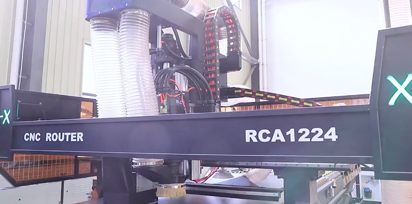
For a nesting center such as the Roctech RCA1224, the machining test should be performed on the actual production material — 18 mm particleboard with melamine coating — since the material's compressibility affects results. Cut a 200 mm × 200 mm square, drill four holes at known coordinates, and measure the results. Deviation between nominal and actual hole positions should remain within ±0.1 mm on a machine with fresh tools and proper vacuum hold-down.
Practical Considerations for Busy Shops
Three operational rules make accuracy testing sustainable:
First, test at the beginning of each
Looking for more information about our CNC machines and services? Contact us today.
Contact
Previous:Turn-Mill Centers in the Post-Mass-Customization Era: Bridging Wood, Foam, and Light Alloy Machining
Next:Nesting CNC Routers Reshape Office Furniture Production Economics